When commissioning a reverse engineering project, many engineers expect to receive a CAD file they can easily modify in SolidWorks or Fusion 360. However, they are often disappointed to receive a massive, sluggish STEP file containing thousands of tiny, freeform surface patches.
This is the result of Auto-Surfacing (or automatic surface fitting), a process that wraps a digital "shrink wrap" over the raw 3D scan mesh. While fast, it produces a file with no parametric history—meaning you cannot change a hole diameter, adjust a pocket depth, or edit a wall thickness.
To get a truly usable file, you need Parametric CAD Reconstruction.
What is Auto-Surfacing?
Auto-surfacing is a software-automated process. The computer analyzes the millions of points in a 3D scan mesh and automatically divides the surface into a grid of NURBS (Non-Uniform Rational B-Splines) patches.
- The Pros: It is extremely fast (taking minutes) and captures organic, complex, freeform shapes (like sculptures or clay models) with high accuracy.
- The Cons: The resulting file has zero design intent. A cylinder isn't recognized as a cylinder with a radius; it is just a collection of curved patches. There is no feature tree, making edits virtually impossible. Furthermore, auto-surfacing captures every defect, scratch, and wear mark present on the physical part.
What is Parametric CAD Reconstruction?
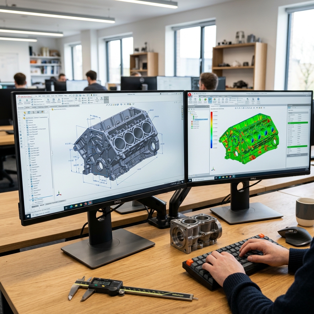
Parametric CAD reconstruction is a manual engineering process. A CAD designer imports the 3D scan mesh into specialized software (like Geomagic Design X) and uses the mesh as a high-precision visual guide to sketch geometric shapes, extrude features, define sketch relations, and rebuild the part from scratch.
- The Pros: You receive a clean, native SolidWorks or STEP file with a fully functional feature tree. Cylinders are modeled as cylinders, planes as perfect planes, and draft angles are standardized. Crucially, the engineer restores the design intent—correcting physical wear, straightening bent flanges, and aligning holes to a logical coordinate system.
- The Cons: It requires significant engineering time and expertise, making it more expensive upfront than auto-surfacing.
| Feature | Auto-Surfacing (Automatic) | Parametric CAD (Manual Engineering) |
|---|---|---|
| Feature History Tree | No (Static solid/surface) | Yes (Fully editable sketch tree) |
| Intent Restoration | No (Captures all wear and defects) | Yes (Normalizes tolerances and dimensions) |
| Modification Ease | Hard (Cannot edit sketch dimensions) | Easy (Double-click any dimension to change) |
| File Size | Large (Heavy NURBS data) | Small (Lightweight parametric features) |
| Best Used For | Sculptures, organic bodies, art | Mechanical components, castings, assemblies |
When to Choose Parametric CAD
If your goal is to manufacture the part—whether by CNC milling, injection molding, or casting—you almost certainly need a parametric model. A machinist cannot easily program a toolpath on a part comprised of thousands of tiny NURBS patches, and injection mold designers need clean draft angles to pull parts from the mold.
At Replix3D, we don't rely on automatic buttons. Our engineers manually reconstruct every mechanical part, ensuring that hole patterns align, threads are standard, and the model is fully optimized for your production line.
Ready to get a clean CAD model from your physical part? Check out our Reverse Engineering Services.