Sending a CAD file to a 3D printing service and getting a perfect part back is not guaranteed. Every week, our engineers receive files with issues that will either cause the print to fail entirely or produce a part that looks correct but breaks the moment stress is applied.
The solution is Design for Manufacturing (DFM) — a set of design principles that bridge the gap between a great CAD model and a great physical part. Here are the seven rules we apply to every file we receive.
Rule 1: Minimum Wall Thickness
The most common failure mode in FDM (Fused Deposition Modeling) printing is walls that are too thin. If a wall is thinner than 1.2mm (2 nozzle widths), the slicer software may not be able to generate a valid toolpath for it — resulting in the wall simply disappearing in the final print.
The fix: Set a minimum wall thickness of 1.5mm for functional FDM parts. For resin printing, you can go as low as 0.8mm due to the higher resolution of photopolymerization.
Rule 2: Overhangs and Support Structures
FDM printers deposit material onto existing material. When a feature extends horizontally beyond 45 degrees from vertical, it starts to "sag" without support. Supports can be removed after printing, but they leave surface marks and require extra post-processing time.
Smart design tip: Reorient your model on the build plate to minimize overhangs. A bracket that prints vertically may have zero overhangs, while the same bracket printed horizontally may require supports everywhere.
Rule 3: Tolerances for Mating Parts
If you design two parts that are supposed to fit together — a shaft and a hole, a lid and a box — you cannot use the exact same dimension for both. FDM parts typically have a dimensional variance of ±0.3mm.
Standard clearances for FDM:
- Loose fit (sliding, easy to remove): add 0.4mm total clearance
- Press fit (tight, requires force): add 0.1–0.2mm clearance
- Snap fit: add 0.3mm and use flexible materials like TPU or PLA
Rule 4: Hole Diameter Compensation
Circular holes in FDM prints always come out slightly smaller than designed. This is due to the way the nozzle deposits material along the perimeter — the inner radius tends to shrink by approximately 0.2mm.
The fix: For precision holes (bolt holes, bearing seats), add 0.2mm to the diameter in your CAD model. For example, if you need a 6.0mm bolt hole, design it at 6.2mm.
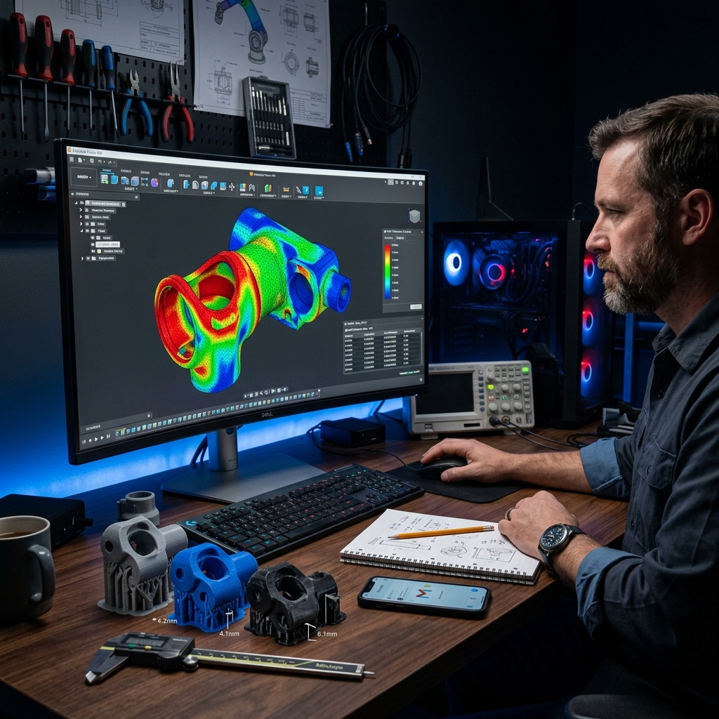
Rule 5: Layer Orientation and Part Strength
FDM parts are inherently anisotropic — they are significantly stronger in the X and Y axes than they are in the Z axis (the stacking direction). A flat layer peel is much weaker than an in-plane shear.
The fix: Design and orient your part so that the primary stress direction is horizontal, not vertical. If your part must resist bending forces along a specific axis, communicate this to your print service so they can orient the model optimally.
Rule 6: Sharp Internal Corners
Sharp internal corners (0° radius) concentrate stress and are also impossible for a rotating endmill or a round nozzle to produce perfectly. In FDM, internal corners will have a small radius equal to the nozzle diameter (typically 0.4mm).
The fix: Add a fillet of at least 0.5mm to all internal corners. This both improves part strength and produces cleaner geometry.
Rule 7: Text and Fine Surface Details
Embossed or debossed text is a great way to label parts, but there are limits to what FDM can reproduce clearly.
- Minimum embossed text height: 1.5mm
- Minimum text depth (debossed): 0.5mm
- Minimum font stroke width: 0.8mm
For highly detailed surface text — logos, serial numbers, fine graphics — resin printing is strongly recommended over FDM.
We Check All of This For Free
At Replix3D, every quote includes a free DFM review. We examine your file against all of these criteria before quoting or printing anything. If we spot a problem, we will tell you exactly what it is and how to fix it — no extra charge.
Ready to get a quote on your next part? Upload your file today and receive a DFM assessment within 1 business day.